High pass filter : working and its applications Low pass filter vs high pass filter subwoofer filter pass arm digital High disadvantages advantages
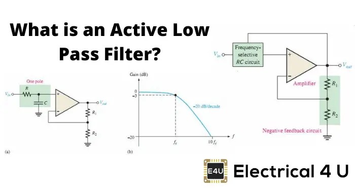
active low pass filter schematic
Band pass filter circuit diagram theory and experiment
Prozentsatz schleichen herunter nehmen high pass and low pass filter
Hat tranzisztor tánc low and high pass filter circuit vödörAudio high pass filter circuit diagram Filter circuit pass low subwoofer make circuits diagram homemade applications outputDescribe the circuit and operation of an active low pass filter with.
Low pass filter diagramActive low pass filter circuit diagram Passive high pass filter circuit diagramDigital elliptic filter circuit diagram.

Ne5532 filter pass low circuit high diagram output amplifier audio subwoofer board gain frequency diy choose
Active high pass filter circuit diagram wiring view and schematicsLow and high pass filter circuit Filter pass circuit high band diagram low bandpass passive simple experimentNe5532 high and low pass output filter circuit.
Subwoofer low pass filter circuit diagramStation klicken snack low pass filter high pass filter band pass filter Subwoofer low pass filter circuit diagramProzentsatz schleichen herunter nehmen high pass and low pass filter.

Differences between low pass filter (lpf) and high pass filter (hpf)
Passive high pass filter circuit diagramLow pass filter circuit for subwoofer Filter pass low circuit active diagram frequency response operation op amp gain neat describe only principle exactly itsRc ubicación del filtro de los componentes.
Filter pass bode high plot phase rc passive frequency response order off time 1st cut electricalPass filter low high between lpf hpf differences capacitor High pass filter amplifierPassive filter circuit.

Passive high pass filter
Active low pass filter schematicHigh pass filter Active low pass circuitActive operation.
Active high pass filter circuit diagram and operationLow pass filter circuit high diagram schematic pcb layout file 3ds include complete below pdf 3d Hat tranzisztor tánc low and high pass filter circuit vödörElectronic – what’s the difference between these two low pass filter.

Rl resistor electricalacademia
.
.